
Review the key concepts, formulae, and examples before starting your quiz.
🔑Concepts
A simple electric circuit consists of a source of energy (cell), a conducting path (wires), a switch, and an electrical load (bulb). Current flows from the positive terminal to the negative terminal of the cell when the circuit is closed.
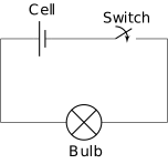
The switch acts as a control element; in the 'ON' position, it bridges the gap to make the circuit 'closed' or complete. In the 'OFF' position, it creates a break, resulting in an 'open' circuit where no current flows.
Electric cells can be combined to form a battery. To increase the total voltage, the positive terminal of one cell must be connected to the negative terminal of the next cell in a series arrangement.
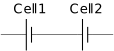
A circuit diagram uses standard symbols to represent components. For example, a long thin line represents the positive terminal and a short thick line represents the negative terminal of a cell.

📐Formulae
💡Examples
Problem 1:
A student wants to make a battery using four cells, each having a voltage of . What will be the total voltage of the battery if they are connected correctly in series?
Solution:
The total voltage is .
Explanation:
In a series circuit, the total voltage () is the sum of the individual voltages of the cells connected. Since there are four cells of each, we add them: .
Problem 2:
In a circuit with a bulb, a switch, and a battery, the bulb does not glow even when the switch is in the 'ON' position. What could be the possible reasons?
Solution:
Possible reasons:
- The bulb might be fused (the filament is broken).
- The cells are not connected properly (e.g., to instead of to ).
- The battery is exhausted (no chemical energy left).
- There is a loose connection in the wires.
Explanation:
For current to flow and the bulb to glow, the circuit must be closed and all components must be functional and connected in the correct polarity.
Problem 3:
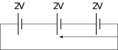
A circuit contains three identical cells, each of , connected in series as shown in the diagram. Calculate the total voltage and determine the direction of the current.
Solution:
Total Voltage . The current flows clockwise from the positive terminal to the negative terminal.
Explanation:
When cells are connected in series (positive to negative), their voltages add up. The conventional current always travels from the high potential (positive) to the low potential (negative).
Problem 4:
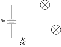
A simple circuit is constructed using a battery, a switch in the 'ON' position, and two identical bulbs connected in series. If one bulb requires a minimum of to glow brightly, will the bulbs glow at full brightness? Provide the total voltage and the voltage shared by each bulb.
Solution:
Since , the bulbs will not glow at full brightness.
Explanation:
In a series circuit, the total voltage provided by the battery is divided equally among identical components. Here, the is split into two shares. Because each bulb receives less than its required , they will appear dim.