
Electricity - CIRCUIT DIAGRAM11.3 CIRCUIT DIAGRAM11.3 CIRCUIT DIAGRAM11.3 CIRCUIT DIAGRAM11.3 CIRCUIT DIAGRAM
Review the key concepts, formulae, and examples before starting your quiz.
🔑Concepts
A circuit diagram is a simplified graphical representation of an electrical circuit using standardized symbols for components such as cells, resistors, switches, and meters.
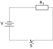
The long vertical line in a cell symbol represents the positive terminal, while the short, thicker vertical line represents the negative terminal. A combination of cells is called a battery.

An Ammeter is always connected in series to measure current (), whereas a Voltmeter is always connected in parallel across the component to measure potential difference ().
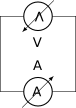
A 'plug key' or switch acts as a control element; when open, the circuit is broken and no current flows, and when closed (indicated by a dot), the circuit is complete.
📐Formulae
💡Examples
Problem 1:
A circuit contains a battery of cells of each, a resistor, an resistor, and a resistor, all connected in series with a closed plug key and an ammeter. Calculate the reading shown by the ammeter.
Solution:
Total Potential Difference . Since resistors are in series, Total Resistance . Using Ohm's Law:
Explanation:
In a series circuit, the total resistance is the sum of individual resistances. The ammeter measures the total current flowing through the circuit, which is calculated using the total voltage and total resistance.
Problem 2:
Calculate the equivalent resistance of two resistors of and when they are connected in parallel in a circuit diagram.
Solution:
Given and . Formula for parallel resistance:
Explanation:
When resistors are connected in parallel, the reciprocal of the equivalent resistance is equal to the sum of the reciprocals of the individual resistances.
Problem 3:
Draw a circuit diagram representing a battery of four cells of each, a resistor, a resistor, and an ammeter, all connected in series with a closed switch. Calculate the total potential difference and the reading shown by the ammeter.
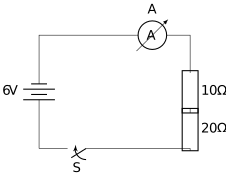
Solution:
- Total potential difference (): Since there are four cells of each in series, .
- Total resistance (): Since the resistors are in series, .
- Current (): Using Ohm's Law, . The ammeter reading is .
Explanation:
In a series circuit, the total voltage is the sum of the individual cell voltages, and the total resistance is the sum of individual resistances. The ammeter measures the same current flowing through all components in a series loop.
Problem 4:
Consider a circuit where two resistors of and are connected in parallel to a battery. A voltmeter is connected across the resistor. Determine the reading of the voltmeter and the total current drawn from the battery.
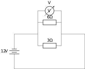
Solution:
- Voltmeter reading: In a parallel circuit, the potential difference across each branch is the same as the supply voltage. Therefore, the voltmeter reading across the resistor is .
- Equivalent resistance (): , so .
- Total current (): .
Explanation:
A voltmeter is always connected in parallel. In a parallel arrangement, the voltage remains constant across all branches, while the total current is the sum of the currents through each branch (or calculated via equivalent resistance).