
Review the key concepts, formulae, and examples before starting your quiz.
🔑Concepts
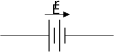
The Internal Resistance of a Cell: Every cell has an inherent resistance to the flow of current within it, denoted as . This results in a terminal voltage that is less than the EMF when current is being drawn, expressed as .
Principle of a Potentiometer: It works on the principle that for a uniform wire carrying a constant current, the potential drop across any segment of the wire is directly proportional to its length, i.e., or , where is the potential gradient.
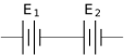
Cells in Series: When cells are connected in series, the equivalent EMF is the sum of individual EMFs, and the equivalent internal resistance is the sum of individual internal resistances.
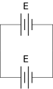
Cells in Parallel: When identical cells are connected in parallel, the equivalent EMF remains the same as a single cell, but the equivalent internal resistance decreases, following the reciprocal rule for parallel resistors.
Sensitivity of Potentiometer: The sensitivity of a potentiometer can be increased by decreasing the potential gradient . This is achieved by either increasing the length of the wire or decreasing the current in the primary circuit.

📐Formulae
💡Examples
Problem 1:
A cell of EMF is balanced against a length of on a potentiometer wire. When a resistance of is connected across the cell, the balancing length becomes . Calculate the internal resistance of the cell.
Solution:
Given , , and . Using the formula , we get .
Explanation:
The internal resistance is found by comparing the balancing length of the cell in an open circuit () to the balancing length when shunted by a known resistor ().
Problem 2:
In a potentiometer arrangement, a cell of EMF gives a balance point at length of the wire. If the cell is replaced by another cell and the balance point shifts to , what is the EMF of the second cell?
Solution:
Using the principle , we have , , and . Therefore, .
Explanation:
Since the potential gradient is constant for the same potentiometer setup, the ratio of the EMFs is equal to the ratio of their respective balancing lengths.
Problem 3:
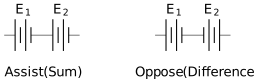
Two cells of EMFs and are connected in series to assist each other and then in series to oppose each other. The balance points are found at and respectively. Calculate the ratio .
Solution:
In the 'assist' mode, the total EMF is . In the 'oppose' mode, the total EMF is . According to the potentiometer principle: Dividing the two equations:
Explanation:
This is the comparison of EMFs using the sum and difference method. The ratio of the EMFs is derived from the ratio of the balancing lengths for the combined configurations.