
Review the key concepts, formulae, and examples before starting your quiz.
🔑Concepts
Electric current is the rate of flow of charge, where . In metallic conductors, current is the drift of free electrons through a lattice of positive ions.
Ohm's Law states that for a conductor at constant temperature, the current is directly proportional to the potential difference across it, expressed as .
Resistivity () is an intrinsic property of a material. Resistance () depends on the material's resistivity, its length (), and its cross-sectional area () as defined by .
Kirchhoff's First Law (Current Law) is a consequence of the conservation of charge: the sum of currents entering a junction equals the sum of currents leaving the junction ().

Kirchhoff's Second Law (Voltage Law) is a consequence of the conservation of energy: the algebraic sum of the electromotive forces (EMF) in any closed loop is equal to the algebraic sum of the potential drops ().
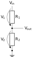
Potential dividers use two or more resistors in series to provide a fraction of the source voltage. The output voltage is determined by the ratio of the resistances.
📐Formulae
💡Examples
Problem 1:
A copper wire has a cross-sectional area of and carries a current of . If the number density of free electrons in copper is , calculate the drift velocity of the electrons.
Solution:
Using the formula , we rearrange for :
Explanation:
This demonstrates that while the signal of electricity travels near the speed of light, the actual 'particles' (electrons) move very slowly through the lattice of the conductor.
Problem 2:
A battery with an EMF of and an internal resistance of is connected to a resistor of . Determine the terminal potential difference of the battery.
Solution:
First, find the total current using : Now, find the terminal potential difference :
Explanation:
The terminal potential difference is lower than the EMF because some energy is dissipated as heat within the battery's internal resistance ( 'lost volts').
Problem 3:
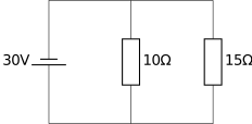
Calculate the power dissipated in a resistor when it is connected in parallel with a resistor, both of which are connected to a ideal power supply.
Solution:
In a parallel circuit, the potential difference across each branch is equal to the supply voltage. Therefore, the voltage across the resistor is: Using the power formula:
Explanation:
Because the resistors are in parallel and the supply is ideal (no internal resistance), each resistor experiences the full . The power dissipated depends only on that voltage and its individual resistance.
Problem 4:
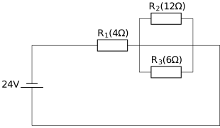
A circuit consists of a ideal DC power supply connected in series with a resistor () and a parallel combination of two resistors: a resistor () and a resistor (). Calculate the total current flowing from the power supply and the potential difference across the parallel combination.
Solution:
Explanation:
First, the equivalent resistance of the parallel branch ( and ) is calculated using the reciprocal formula. This equivalent resistance is then added to the series resistor to find the total circuit resistance. Ohm's law is applied to the entire circuit to find the total current. Finally, the potential difference across the parallel section is found by multiplying the total current by the equivalent resistance of that specific section.