
Review the key concepts, formulae, and examples before starting your quiz.
🔑Concepts
Electric current is the flow of charge (usually electrons) around a circuit. For a current to flow, there must be a complete, closed loop and a source of potential difference (like a cell or battery).
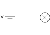
Circuit symbols are used to represent components in a standardized way. A cell provides electrical energy, while a battery consists of multiple cells connected together.
Ammeters measure current in Amperes () and must always be connected in series with the component being measured. Voltmeters measure potential difference in Volts () and must be connected in parallel across the component.
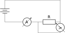
In a series circuit, there is only one path for the current to flow. The current is the same at all points in the circuit: .
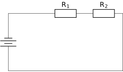
Resistance is a measure of how much a component opposes the flow of current. It is measured in Ohms (). A higher resistance results in a lower current for a given voltage.

📐Formulae
💡Examples
Problem 1:
A battery is connected to a resistor. An ammeter shows a current of . Calculate the resistance of the resistor.
Solution:
Explanation:
By applying the Ohm's Law formula , we divide the potential difference by the current to find the resistance in Ohms.
Problem 2:
Two resistors, and , are connected in a series circuit. What is the total resistance provided to the battery?
Solution:
Explanation:
In a series circuit, the total resistance is the sum of all individual resistances along the path.
Problem 3:
A circuit has a resistance of and a voltage source of . Calculate the current flowing through the circuit.
Solution:
Explanation:
Using the rearranged Ohm's Law formula , the current is calculated as Amperes.
Problem 4:
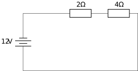
A circuit contains a battery and two resistors connected in series: and . Calculate the current flowing through the resistor.
Solution:
Explanation:
In a series circuit, we first find the total resistance by adding the individual resistances. Since the current is the same everywhere in a series circuit, the current through the resistor is the same as the total current, which is .
Problem 5:
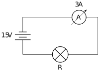
A student sets up a circuit with a power supply and a single bulb. The ammeter in the circuit reads . What is the resistance of the bulb?
Solution:
Explanation:
To find the resistance, we use Ohm's Law rearranged as . Dividing the voltage () by the current () gives a resistance of .