
Review the key concepts, formulae, and examples before starting your quiz.
🔑Concepts
Electric Current: The rate of flow of charge, where conventional current flows from the positive terminal to the negative terminal of a power source.
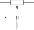
Potential Difference (Voltage): The energy transferred per unit charge as it moves between two points in a circuit, measured in Volts ().

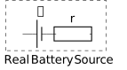
Electromotive Force (EMF) and Internal Resistance: The total energy supplied by a source per unit charge. Real batteries have an internal resistance () which causes a 'lost volts' effect () when current flows.
Kirchhoff's First Law (Current Law): The sum of currents entering a junction equals the sum of currents leaving it, based on the conservation of charge.
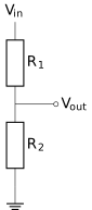
Potential Dividers: A circuit used to provide a specific output voltage () by splitting the supply voltage between two resistors in series.
📐Formulae
or
💡Examples
Problem 1:
A battery with an EMF of and an internal resistance of is connected to an external resistor of . Calculate the terminal potential difference across the battery.
Solution:
First, find the total resistance: . Next, calculate the circuit current: . Finally, calculate the terminal voltage: .
Explanation:
The terminal potential difference is always less than the EMF when a current flows because of the voltage drop across the internal resistance ().
Problem 2:
Calculate the total resistance of three resistors (, , and ) connected in parallel.
Solution:
Using the parallel resistance formula: . This simplifies to . Therefore, .
Explanation:
In a parallel circuit, the total resistance is always less than the smallest individual resistance.
Problem 3:
A electric kettle is connected to a mains supply. Calculate the current flowing through the element and its resistance.
Solution:
Using , current . Using , resistance .
Explanation:
Power must be converted to Watts () before using the standard formulae.
Problem 4:
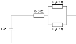
In the following series-parallel circuit, find the total current supplied by the battery. The resistors are , , and .
Solution:
- Find the equivalent resistance of the parallel branch ( and ):
- Calculate total resistance ():
- Use Ohm's Law to find total current:
Explanation:
We first simplify the parallel combination of and into a single equivalent resistor, then add it to because they are in series. Finally, we use the battery voltage and total resistance to find the source current.
Problem 5:
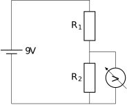
A potential divider circuit is used to provide a variable output voltage. The input voltage is , and the circuit consists of a fixed resistor and a thermistor . At a certain temperature, the resistance of the thermistor is . Calculate the output voltage across the thermistor and determine the current flowing through the circuit.
Solution:
For the current :
Explanation:
In a potential divider circuit, the input voltage is shared between resistors in series in proportion to their resistance. The output voltage across the second resistor is found using the potential divider formula. The total current is found by dividing the supply voltage by the sum of all resistances in the series loop.