
Review the key concepts, formulae, and examples before starting your quiz.
🔑Concepts
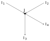
Kirchhoff's First Law (Junction Rule): This law is based on the conservation of charge. It states that the algebraic sum of currents meeting at a junction in an electrical circuit is zero, i.e., . Currents entering the junction are taken as positive, while currents leaving are negative.
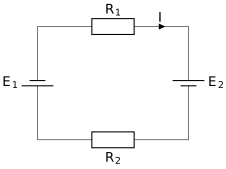
Kirchhoff's Second Law (Loop Rule): Based on the conservation of energy, it states that in any closed loop of a network, the algebraic sum of changes in potential is zero. This means the sum of e.m.f.s is equal to the sum of the products of current and resistance: .
Wheatstone Bridge Principle: An arrangement of four resistances and forming a bridge. The bridge is said to be balanced when no current flows through the galvanometer (). At this condition, the ratio of resistances in adjacent arms is equal: .
The Potentiometer: A sensitive device used to measure e.m.f. or potential difference without drawing any current from the source. It works on the principle that the potential drop across a segment of a uniform wire is directly proportional to its length (), provided a constant current flows through it.
📐Formulae
💡Examples
Problem 1:
In a Meter Bridge, the null point is found at a distance of from end when a resistor is in the left gap and an unknown resistor is in the right gap. Calculate the value of .
Solution:
Given and . Using the Meter Bridge formula: . Substituting the values: .
Explanation:
The unknown resistance is found by applying the balanced Wheatstone Bridge condition adapted for the lengths of the wire.
Problem 2:
A potentiometer wire has a length of and resistance . A battery of is connected across it. Calculate the potential gradient .
Solution:
Total length , Resistance , Voltage . Potential gradient . So, .
Explanation:
Potential gradient is the potential drop per unit length of the potentiometer wire, which determines the sensitivity of the instrument.
Problem 3:
In a potentiometer experiment, the balancing length for a cell in open circuit is . When a resistor of is connected across the cell, the balancing length shifts to . Find the internal resistance of the cell.
Solution:
Given , , and . Using the formula : .
Explanation:
The internal resistance is calculated by comparing the balancing lengths of the cell in an open circuit (EMF) and a closed circuit (Terminal Voltage).
Problem 4:
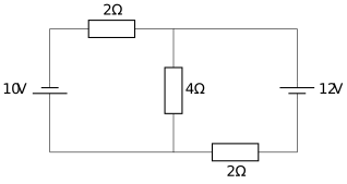
Determine the current flowing through the resistor in the following circuit using Kirchhoff's Laws. The circuit consists of two loops with batteries and and resistors , , and .
Solution:
Let be the current from and be the current from . At the central branch, the current is . Applying Loop Rule to Loop 1 (left): Applying Loop Rule to Loop 2 (right): Multiplying (1) by 3 and (2) by 2: Subtracting: . Substitute in (1): . Current through resistor: .
Explanation:
We used Kirchhoff's Voltage Law (KVL) for two independent loops and Kirchhoff's Current Law (KCL) at the junction to solve for the individual branch currents.
Problem 5:
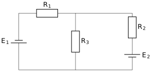
In the circuit shown, two batteries and are connected with three resistors , , and . Using Kirchhoff's laws, calculate the current flowing through the resistor .
Solution:
Let the current from be and from be . At the junction, they combine so that .
Applying Kirchhoff's Voltage Law (KVL) to the left loop (clockwise):
Applying KVL to the right loop (counter-clockwise):
Multiplying (1) by 3 and (2) by 4:
Subtracting the first from the second:
Substitute into (1):
Calculate :
Explanation:
We apply Kirchhoff's First Law at the central node and Kirchhoff's Second Law to the two independent loops. The negative sign for simply indicates that the current actually flows in the opposite direction to our initial assumption.