krit.club logo

Alternating Current - Power in AC Circuits

Grade 12CBSEPhysics

Review the key concepts, formulae, and examples before starting your quiz.

πŸ”‘Concepts

β€’

Instantaneous power in an AC circuit is the product of instantaneous voltage v=V0sin⁑(Ο‰t)v = V_0 \sin(\omega t) and instantaneous current i=I0sin⁑(Ο‰t+Ο•)i = I_0 \sin(\omega t + \phi). Over a complete cycle, the average power dissipated is Pavg=VrmsIrmscos⁑ϕP_{avg} = V_{rms} I_{rms} \cos \phi, where cos⁑ϕ\cos \phi is the power factor.

β€’

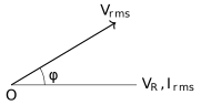
The term cos⁑ϕ\cos \phi is known as the Power Factor. In a purely resistive circuit, Ο•=0∘\phi = 0^\circ and cos⁑ϕ=1\cos \phi = 1 (Maximum power). In purely inductive or capacitive circuits, Ο•=90∘\phi = 90^\circ and cos⁑ϕ=0\cos \phi = 0 (Zero power).

Phasor diagram showing the phase angle phi between voltage and current.
β€’

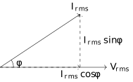
Wattless Current: The component of current Irmssin⁑ϕI_{rms} \sin \phi which does not consume any power in the circuit is called wattless current. This happens because the phase difference between this current component and voltage is Ο€2\frac{\pi}{2}.

Phasor components of RMS current showing wattful and wattless components.
β€’

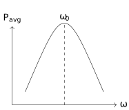
Power at Resonance: At resonance, XL=XCX_L = X_C, so Z=RZ = R. The phase difference Ο•\phi becomes 00. Consequently, the power factor cos⁑ϕ=1\cos \phi = 1, and the power dissipation is maximum, given by P=VrmsIrms=Vrms2RP = V_{rms} I_{rms} = \frac{V_{rms}^2}{R}.

Graph showing average power vs angular frequency reaching a peak at resonance frequency.

πŸ“Formulae

Pinst=vβ‹…iP_{inst} = v \cdot i

Pavg=VrmsIrmscos⁑ϕP_{avg} = V_{rms} I_{rms} \cos \phi

Vrms=V02,Irms=I02V_{rms} = \frac{V_0}{\sqrt{2}}, \quad I_{rms} = \frac{I_0}{\sqrt{2}}

PowerΒ Factor=cos⁑ϕ=RZ\text{Power Factor} = \cos \phi = \frac{R}{Z}

Z=R2+(XLβˆ’XC)2Z = \sqrt{R^2 + (X_L - X_C)^2}

Pavg=Irms2RP_{avg} = I_{rms}^2 R

Iwattless=Irmssin⁑ϕI_{wattless} = I_{rms} \sin \phi

πŸ’‘Examples

Problem 1:

A series LCR circuit with R=80 ΩR = 80 \, \Omega, XL=100 ΩX_L = 100 \, \Omega, and XC=40 ΩX_C = 40 \, \Omega is connected to a 200 V,50 Hz200 \, V, 50 \, Hz AC supply. Calculate the power factor and the average power dissipated in the circuit.

Solution:

  1. First, calculate the impedance ZZ: Z=R2+(XLβˆ’XC)2=802+(100βˆ’40)2=802+602=6400+3600=100 ΩZ = \sqrt{R^2 + (X_L - X_C)^2} = \sqrt{80^2 + (100 - 40)^2} = \sqrt{80^2 + 60^2} = \sqrt{6400 + 3600} = 100 \, \Omega.

  2. Calculate the Power Factor: cos⁑ϕ=RZ=80100=0.8\cos \phi = \frac{R}{Z} = \frac{80}{100} = 0.8.

  3. Calculate IrmsI_{rms}: Irms=VrmsZ=200100=2 AI_{rms} = \frac{V_{rms}}{Z} = \frac{200}{100} = 2 \, A.

  4. Calculate Average Power: Pavg=VrmsIrmscos⁑ϕ=200Γ—2Γ—0.8=320 WP_{avg} = V_{rms} I_{rms} \cos \phi = 200 \times 2 \times 0.8 = 320 \, W.

Explanation:

The power factor is the ratio of resistance to impedance. The average power is the product of the effective voltage, effective current, and the power factor. Alternatively, Pavg=Irms2R=22Γ—80=320 WP_{avg} = I_{rms}^2 R = 2^2 \times 80 = 320 \, W gives the same result.

Problem 2:

Show that the average power consumed by a pure inductor over one complete cycle of AC is zero.

Solution:

For a pure inductor, the current ii lags the voltage vv by a phase angle of Ο€2\frac{\pi}{2}. If v=Vmsin⁑(Ο‰t)v = V_m \sin(\omega t), then i=Imsin⁑(Ο‰tβˆ’Ο€2)=βˆ’Imcos⁑(Ο‰t)i = I_m \sin(\omega t - \frac{\pi}{2}) = -I_m \cos(\omega t). Pavg=1T∫0Tvβ‹…i dt=1T∫0T(Vmsin⁑ωt)(βˆ’Imcos⁑ωt) dtP_{avg} = \frac{1}{T} \int_0^T v \cdot i \, dt = \frac{1}{T} \int_0^T (V_m \sin \omega t) (-I_m \cos \omega t) \, dt Pavg=βˆ’VmIm2T∫0Tsin⁑(2Ο‰t) dtP_{avg} = -\frac{V_m I_m}{2T} \int_0^T \sin(2\omega t) \, dt. Since the integral of a sine function over a full period is zero, Pavg=0P_{avg} = 0.

Explanation:

Mathematically, the phase difference Ο•\phi is 90∘90^\circ. Using the formula Pavg=VrmsIrmscos⁑90∘P_{avg} = V_{rms} I_{rms} \cos 90^\circ, since cos⁑90∘=0\cos 90^\circ = 0, the power dissipation is zero.

Problem 3:

An AC voltage v=282sin⁑(100Ο€t)v = 282 \sin(100\pi t) is applied to a resistor of 100 Ω100 \, \Omega. Calculate (i) the RMS voltage, (ii) the RMS current, and (iii) the average power dissipated over a complete cycle.
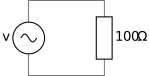
A simple AC circuit consisting of a sinusoidal voltage source connected in series with a 100 ohm resistor.

Solution:

From the equation v=V0sin⁑(Ο‰t)v = V_0 \sin(\omega t), we have: V0=282 VV_0 = 282 \, V

(i) RMS voltage: Vrms=V02=2821.414β‰ˆ200 VV_{rms} = \frac{V_0}{\sqrt{2}} = \frac{282}{1.414} \approx 200 \, V

(ii) RMS current: Irms=VrmsR=200100=2 AI_{rms} = \frac{V_{rms}}{R} = \frac{200}{100} = 2 \, A

(iii) Average power dissipated: Pavg=VrmsIrms=200Γ—2=400 WP_{avg} = V_{rms} I_{rms} = 200 \times 2 = 400 \, W Alternatively: Pavg=Irms2R=22Γ—100=4Γ—100=400 WP_{avg} = I_{rms}^2 R = 2^2 \times 100 = 4 \times 100 = 400 \, W

Explanation:

In a purely resistive circuit, the phase difference Ο•\phi is zero, making the power factor cos⁑ϕ=1\cos \phi = 1. Thus, the average power is simply the product of the RMS voltage and RMS current.

Problem 4:

A capacitor of capacitance CC and a resistor of R=30 ΩR = 30 \, \Omega are connected in series to an AC source of 200 V,50 Hz200 \, V, 50 \, Hz. If the power factor of the circuit is 0.60.6, calculate the capacitance of the capacitor.
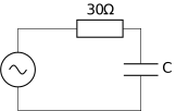
An AC series circuit containing a sinusoidal source, a 30 ohm resistor, and a capacitor C.

Solution:

Given: Vrms=200 VV_{rms} = 200 \, V f=50 Hzf = 50 \, Hz R=30 ΩR = 30 \, \Omega cos⁑ϕ=0.6\cos \phi = 0.6

Step 1: Find Impedance ZZ: cos⁑ϕ=RZβ€…β€ŠβŸΉβ€…β€Š0.6=30Z\cos \phi = \frac{R}{Z} \implies 0.6 = \frac{30}{Z} Z=300.6=50 ΩZ = \frac{30}{0.6} = 50 \, \Omega

Step 2: Find Capacitive Reactance XCX_C: Z=R2+XC2β€…β€ŠβŸΉβ€…β€Š502=302+XC2Z = \sqrt{R^2 + X_C^2} \implies 50^2 = 30^2 + X_C^2 2500=900+XC22500 = 900 + X_C^2 XC2=1600β€…β€ŠβŸΉβ€…β€ŠXC=40 ΩX_C^2 = 1600 \implies X_C = 40 \, \Omega

Step 3: Find Capacitance CC: XC=12Ο€fCX_C = \frac{1}{2\pi f C} 40=12Γ—3.14Γ—50Γ—C40 = \frac{1}{2 \times 3.14 \times 50 \times C} C=140Γ—314β‰ˆ7.96Γ—10βˆ’5 F=79.6 μFC = \frac{1}{40 \times 314} \approx 7.96 \times 10^{-5} \, F = 79.6 \, \mu F

Explanation:

The power factor determines the ratio of resistance to the total impedance. By finding the impedance first, we can isolate the capacitive reactance and subsequently calculate the capacitance using the source frequency.